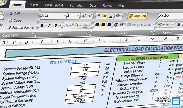


be used as example onelines for system design. This is defined as the rms excitation voltage corresponding to ten-per-cent error current. internal groundedwye isolation transformer are not covered in this document. The first step is to determine the saturation voltage (Vs) for the CT in question. MEP WORK 4k followers More information Transformer Design and Sizing Excel Sheet Calculator Find this Pin and more on Electrical MEP by MEP WORK. This excel sheet calculates the number of turns in primary and secondary and total a.
Transformer design calculation excel free#
(*) Tziouvaras, D.A., et al, Mathematical Models for Current, Voltage, and Coupling Capacitor Voltage Transformers Transformer Design and Sizing Excel Sheet Calculator Free excel sheet for transformer design calculation. In addition, the program has had widespread circulation, and to date there are two utility-user reports of agreement with previous results and no reports of disagreement. To this end, two laboratory examples published in reference (*) were compared against results from this program. nominal current 3000kVA at 480V is 3,613 amps, nominal Z is 5.75. Because this model is new and quite different from those in the literature, testing against real high-current laboratory results was important. SCA (3,011/5.75) X 100 X 1.075 56,293 amps symmetrical RMS. The proof of the pudding is in the eating. Step 1: System simulation and transformer design Step 2: Transformer construction Step 3: System design finalization 3. The current transformer will operate into either a short circuit or a resistive load until the. A current transformer operates with a set primary current and will try to output a constant current to the load, independent of the load. If errors under low current, low burden conditions are of interest, a more elaborate model must be used. Short circuit impedance voltage of the transformer 2- place the secondary on short circuit 3- gradually increase the voltage at the primary up to reach 1-the voltage on primary (U) is not powered zero from U:zero to Usc. Unique to a Current Transformer The current transformer function is different than that of a voltage transformer. This simplifies the solution greatly, with little effect on accuracy. It turns out (can be shown) that, if the excitation current waveform reaches into the saturated region, the part of the waveform in the below-knee-point region has negligible effect on the overall solution. Transformer Losses Total losses (w) Rtr (mille-ohm) Ztr (mille-ohm) Xtr (mille-ohm) Isc (KA) TR.


 0 kommentar(er)
